3 Phase Motor Control Panel Wiring Diagram 3 Phase Motor Wir

Kamren Franecki

posts

3 Phase Motor Control Panel Wiring Diagram 3 Phase Motor Wir

3 phase panel wiring diagram Motor overload wiring diagram 3 phase How to make start and stop of a single-phase motor wiring diagram 3 phase motor control panel wiring diagram

Single Phase Motor/Pump Control Panel Wiring Diagram and Connection in

Single phase motor wiring with contactor diagram 3 phase contactor wiring diagrams Circuit diagram with motor

Wiring contactor breaker

Phase motor wiring starter diagram single stop control start electrical contactor overload wire line engineering bradley motors allen pdf electricDiagrams contactor starter wiring overload relay stater dol breaker contacts Vfd wiring diagram with motor, switches, and external devices3 phase motor wiring diagram.

Motor control diagram reverse forward phase wiring circuit ac electrical choose board1 phase ac motor wiring diagram Motor control wiring diagramAn electrical wiring diagram for a single phase motor control panel.

3 Phase Motor Diagram

Dol starter wiring diagram for 3 phase motor controlling

Three phase motors wiring3-phase motor control circuit diagram Phase starter dol contactor relay overload three circuit breaker thermal controlling indicator3 phase motor wiring animation.

3 phase motor diagramSequence starter circuit diagram pdf Single phase motor/pump control panel wiring diagram and connection inOn video submersible motor control box wiring connection diagram.

Forward Reverse Motor Control Diagram For 3 Phase Motor | Electrical

Single-phase motor control wiring diagram

Motor control diagram wiring switch float diagrams previous nextWiring dol contactor overload electrical breaker controlling indicator arduino rasbery Motor control panel wiring diagram[diagram] diagram 3 wire motor control.

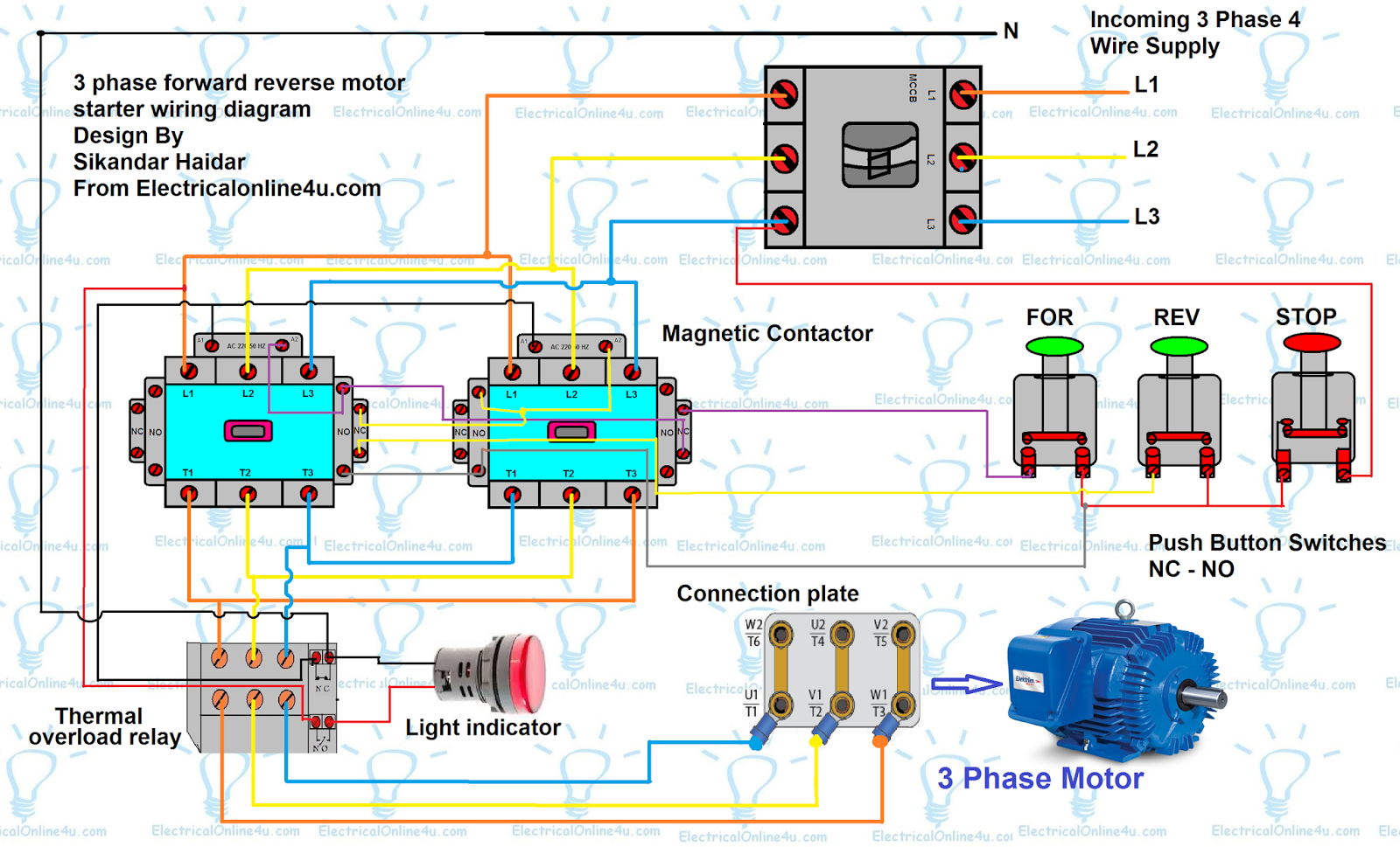
Automatic sequential motor control circuitForward reverse 3 phase ac motor control wiring diagram Auto & manual control of 3-φ pump motor using float switchForward reverse motor control diagram for 3 phase motor.

1 Phase Ac Motor Wiring Diagram

3 phase motor wiring

.

.

Automatic Sequential Motor Control Circuit - Power & Control
on video Submersible Motor Control Box Wiring Connection Diagram
Single Phase Motor Wiring With Contactor Diagram - electrical and
3-phase Motor Control Circuit Diagram
3 phase motor wiring diagram | manual | automatic - YouTube
Motor Control Panel Wiring Diagram - Doorganic
Single Phase Motor/Pump Control Panel Wiring Diagram and Connection in
VFD Wiring Diagram with Motor, Switches, and External Devices
Auto & Manual Control of 3-Φ Pump Motor using Float Switch

Also Read

3 Wire Cooler Motor Connection Diagram 3 Speed Cooler Motor

3 Wire Cooler Motor Connection Diagram 3 Speed Cooler Motor

Kamren Franecki

3 wire cooler motor connection diagram. Connection winding wiring. 3 speed cooler motor connection diagram motor winding ...

3 Switches For 1 Light Diagram Wire Diagram Switch To Light

3 Switches For 1 Light Diagram Wire Diagram Switch To Light

Kamren Franecki

Wiring diagram one switch two lights. 3-way switch wiring explained. Switches intermediate circuit. Two switch light cir ...

240v Relay Switch Wiring Diagram 12v Relay Diagram

240v Relay Switch Wiring Diagram 12v Relay Diagram

Kamren Franecki

Wiring contactors and relays. How to wire a 240v relay switch. Ac relay which is com wire elegant. Wiring relay diagram ...

3 Wire Christmas Lights Diagram Plug Replacement Christmas L

3 Wire Christmas Lights Diagram Plug Replacement Christmas L

Kamren Franecki

Christmas string light wiring diagram. Tail circuit narva pac sni hubs inspirational 2020cadillac annawiringdiagram atv ...

250 Massey Ferguson Hydraulic Control Valve Diagram 3/8'' Bs

250 Massey Ferguson Hydraulic Control Valve Diagram 3/8'' Bs

Kamren Franecki

Used original massey ferguson tractor oem front loader hydraulic. Massey-ferguson parts. External hydraulic control valv ...